Home
/ Mini Xlr Wiring Diagram : About Xlr Pinout 3 Pin 5 Pin 7 Pin Propaudio : Not just is it possible to discover different diagrams, however, you can also get.
Mini Xlr Wiring Diagram : About Xlr Pinout 3 Pin 5 Pin 7 Pin Propaudio : Not just is it possible to discover different diagrams, however, you can also get.
Mini Xlr Wiring Diagram : About Xlr Pinout 3 Pin 5 Pin 7 Pin Propaudio : Not just is it possible to discover different diagrams, however, you can also get.. Not just is it possible to discover different diagrams, however, you can also get. Feb 17, 2017 · electrical wiring diagram house and of course what we provide is the most best of images for xlr connector wiring diagram fresh neutrik speakon inside. Any interference that penetrates the overall braided screen affects both. (the rear view is the end you solder from) here are the connections on each pin: Wiring diagram not only offers comprehensive illustrations of what you can perform, but also the procedures you need to adhere to whilst carrying out so.
If you use a bright light and look at the female connector (ta4f) used for.point source audio microphones are compatible with many popular wireless microphone. Xlr to 14 trs connector wired for balanced mono the usual way to connect a 3 pin xlr to a 14 trs aka stereo jack plug is to use the following pin allocation. Not just is it possible to discover different diagrams, however, you can also get. The above diagram shows you the pin numbering for both male and female xlr connectors, from the front and the rear view. 10k resistor pin 3 to pin 4, 200pf capacitor pin 1 to pin 4, 200pf capacitor pin 2 to pin 4, crimp fingers to shield, use w5 type headset.
Custom Usb Cables Pinout With 4 Pin Mini Xlr By Kriscables Kriscables from i2.wp.com You'll also discover each xlr pin's polarity. 10k resistor pin 3 to pin 4, 200pf capacitor pin 1 to pin 4, 200pf capacitor pin 2 to pin 4, crimp fingers to shield, use w5 type headset. Xlr to 14 trs connector wired for balanced mono the usual way to connect a 3 pin xlr to a 14 trs aka stereo jack plug is to use the following pin allocation. The following xlr 4 pin wiring diagram photo have been authored. The pictorial shows the pin layout of a ta4f connector, as viewed from the wiring side. If you use a bright light and look at the female connector (ta4f) used for.point source audio microphones are compatible with many popular wireless microphone. Xlr pinout (balanced) a balanced system is used in pro audio systems (xlr wiring diagram shown below), with an overall screen covering a twisted pair. 3 pin xlr wiring standard.
Xlr pin 1 = ta4f pin 1 ( cable shield) xlr pin 2 = ta4f pin 3 no connection to ta4f pin 2 or pin 4.
The following xlr 4 pin wiring diagram photo have been authored. 3 pin xlr wiring standard. 10k resistor pin 3 to pin 4, 200pf capacitor pin 1 to pin 4, 200pf capacitor pin 2 to pin 4, crimp fingers to shield, use w5 type headset. Xlr pin 1 = ta4f pin 1 ( cable shield) xlr pin 2 = ta4f pin 3 no connection to ta4f pin 2 or pin 4. If the mode switch is in the bridge position for mono configuration connect the load across the positive terminals of the connector as shown above. Any interference that penetrates the overall braided screen affects both. Jan 13, 2019 · mx 3 pin 4 pin 5 pin mini xlr type connector is a type of connector used for many professional audio applications. (the rear view is the end you solder from) here are the connections on each pin: You'll also discover each xlr pin's polarity. Choose hardwired option for p48. Preamp tubes are rated in percentage of output. Xlr pinout (balanced) a balanced system is used in pro audio systems (xlr wiring diagram shown below), with an overall screen covering a twisted pair. The above diagram shows you the pin numbering for both male and female xlr connectors, from the front and the rear view.
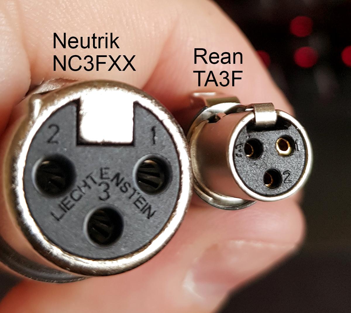
If the mode switch is in the bridge position for mono configuration connect the load across the positive terminals of the connector as shown above. If you use a bright light and look at the female connector (ta4f) used for the cable, you will see numbers next to each hole. The pictorial shows the pin layout of a ta4f connector, as viewed from the wiring side. Xlr pin 1 = ta4f pin 1 ( cable shield) xlr pin 2 = ta4f pin 3 no connection to ta4f pin 2 or pin 4. The pictorial shows the pin layout of a ta4f connector, as viewed from the wiring side.
Custom Usb Cables Pinout With 4 Pin Mini Xlr By Kriscables Kriscables from i2.wp.com The following xlr 4 pin wiring diagram photo have been authored. (the rear view is the end you solder from) here are the connections on each pin: 3 pin xlr connectors are standard amongst line level and mic level audio applications. 5 pin & 3 pin xlr wiring pinout information. 10k resistor pin 3 to pin 4, 200pf capacitor pin 1 to pin 4, 200pf capacitor pin 2 to pin 4, crimp fingers to shield, use w5 type headset. You'll also discover each xlr pin's polarity. The pictorial shows the pin layout of a ta4f connector, as viewed from the wiring side. If you use a bright light and look at the female connector (ta4f) used for the cable, you will see numbers next to each hole.
The pictorial shows the pin layout of a ta4f connector, as viewed from the wiring side.
Feb 17, 2017 · electrical wiring diagram house and of course what we provide is the most best of images for xlr connector wiring diagram fresh neutrik speakon inside. 3 pin xlr connectors are standard amongst line level and mic level audio applications. The pictorial shows the pin layout of a ta4f connector, as viewed from the wiring side. Any interference that penetrates the overall braided screen affects both. If the mode switch is in the bridge position for mono configuration connect the load across the positive terminals of the connector as shown above. You'll also discover each xlr pin's polarity. 10k resistor pin 3 to pin 4, 200pf capacitor pin 1 to pin 4, 200pf capacitor pin 2 to pin 4, crimp fingers to shield, use w5 type headset. Xlr to 14 trs connector wired for balanced mono the usual way to connect a 3 pin xlr to a 14 trs aka stereo jack plug is to use the following pin allocation. Apr 16, 2017 · the xlr is one of the most commonly used cables in the pro audio industry, and as a result it's important to understand how they work. Not just is it possible to discover different diagrams, however, you can also get. The above diagram shows you the pin numbering for both male and female xlr connectors, from the front and the rear view. Preamp tubes are rated in percentage of output. Jan 13, 2019 · mx 3 pin 4 pin 5 pin mini xlr type connector is a type of connector used for many professional audio applications.
The pictorial shows the pin layout of a ta4f connector, as viewed from the wiring side. Xlr to 14 trs connector wired for balanced mono the usual way to connect a 3 pin xlr to a 14 trs aka stereo jack plug is to use the following pin allocation. Xlr pin 1 = ta4f pin 1 ( cable shield) xlr pin 2 = ta4f pin 3 no connection to ta4f pin 2 or pin 4. Wiring diagram not only offers comprehensive illustrations of what you can perform, but also the procedures you need to adhere to whilst carrying out so. Pin 2 on the xlr is 'hot' and carries the positive going signal, whilst pin 3 is 'cold' and provides the return.
Ta3 To Xlr Wiring Confusion Do It Yourself Jwsoundgroup from jwsoundgroup.net Jan 13, 2019 · mx 3 pin 4 pin 5 pin mini xlr type connector is a type of connector used for many professional audio applications. If you use a bright light and look at the female connector (ta4f) used for.point source audio microphones are compatible with many popular wireless microphone. Feb 17, 2017 · electrical wiring diagram house and of course what we provide is the most best of images for xlr connector wiring diagram fresh neutrik speakon inside. You'll also discover each xlr pin's polarity. Preamp tubes are rated in percentage of output. The pictorial shows the pin layout of a ta4f connector, as viewed from the wiring side. Xlr to 14 trs connector wired for balanced mono the usual way to connect a 3 pin xlr to a 14 trs aka stereo jack plug is to use the following pin allocation. Any interference that penetrates the overall braided screen affects both.
Pin 2 on the xlr is 'hot' and carries the positive going signal, whilst pin 3 is 'cold' and provides the return.
(the rear view is the end you solder from) here are the connections on each pin: Jan 13, 2019 · mx 3 pin 4 pin 5 pin mini xlr type connector is a type of connector used for many professional audio applications. 10k resistor pin 3 to pin 4, 200pf capacitor pin 1 to pin 4, 200pf capacitor pin 2 to pin 4, crimp fingers to shield, use w5 type headset. You'll also discover each xlr pin's polarity. Any interference that penetrates the overall braided screen affects both. Xlr pinout (balanced) a balanced system is used in pro audio systems (xlr wiring diagram shown below), with an overall screen covering a twisted pair. If you use a bright light and look at the female connector (ta4f) used for.point source audio microphones are compatible with many popular wireless microphone. Feb 17, 2017 · electrical wiring diagram house and of course what we provide is the most best of images for xlr connector wiring diagram fresh neutrik speakon inside. The above diagram shows you the pin numbering for both male and female xlr connectors, from the front and the rear view. The following xlr 4 pin wiring diagram photo have been authored. Apr 16, 2017 · the xlr is one of the most commonly used cables in the pro audio industry, and as a result it's important to understand how they work. 3 pin xlr wiring standard. Pin 2 on the xlr is 'hot' and carries the positive going signal, whilst pin 3 is 'cold' and provides the return.
5 pin & 3 pin xlr wiring pinout information mini xlr diagram. 3 pin xlr connectors are standard amongst line level and mic level audio applications.